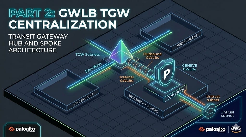
Centralized GWLBe with TGW and Palo Alto VM-Series
In our last post, we explored the Distributed model for the AWS Gateway Load Balancer (GWLB) and Palo Alto VM-Series where we deployed an endpoint in a remote vpc. With that model each new VPC requires its own Gateway Load Balancer Endpoint (GWLBe) and NAT Gateway(NAT-GW) which leads to a higher management overhead and cost.
Today we are moving that deployment into a Centralized Inspection model. By leveraging a Transit Gateway(TGW) we can move our traffic flows towards a central set of endpoints and NAT-GW leading to a smaller set of GWLBe, sub-interfaces/zones in the VM-Series, NAT-GWs, and costs.
This post is an extension of our previous VM-Series and GWLB. We will be transitioning from a single-VPC distributed footprint to a Hub-and-Spoke architecture to achieve centralized inspection.
If you need further instructions on deploying the VM-Series EC2 itself you can find their offical document as of today here. Be on the lookout for an upcoming post where I cover this as well.
Objectives:
- Deploy the TGW and its attachments
- Create/associate the new GWLBes
- Create/adjust route tables to direct the traffic
- Validate the topology with simulated workloads
The TX:
- Spoke VPC: Traffic hits the TGW.
- TGW: Routes traffic to the Security VPC Attachment.
- Security VPC (TGW Subnet): The RTB points 0.0.0.0/0 to the GWLBe.
- GWLBe: Traffic is encapsulated in GENEVE and sent to the VM-Series.
- VM-Series: Inspection occurs. If allowed, it’s sent back to the GWLBe.
- GWLBe Subnet: The RTB points 0.0.0.0/0 to the NAT-GW.
- NAT-GW: Traffic exits to the Internet via the IGW.
The RX:
- NAT-GW Subnet: You must have a route for your Spoke CIDR pointing back to the GWLBe.
- GWLBe Subnet: You must have a route for your Spoke CIDR pointing back to the TGW.
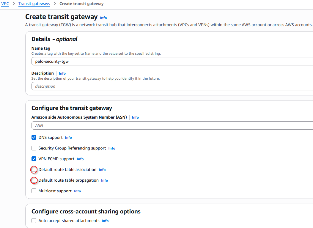
First, we will deploy the Transit Gateway (TGW). Because we are forcing traffic to the security VPC, attachments cannot share the same route table.
- Disable Default Route Table Association: This prevents new VPCs from automatically joining a global routing domain.
- Disable Default Route Table Propagation: This allows us to manually control which subnets are advertised to our security hub.
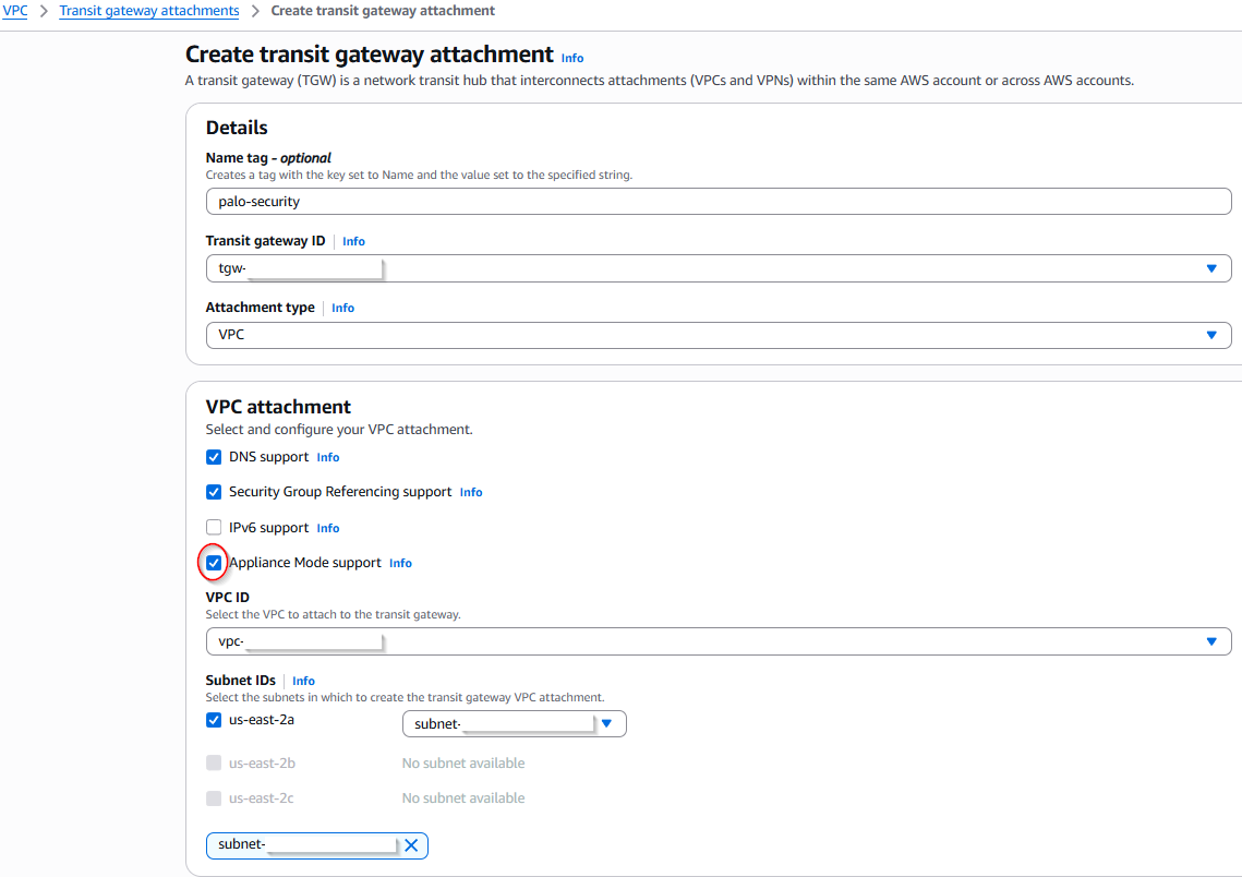
Next is the attachments, one per VPC.
For Multi-AZ each attachment must have Appliance mode enabled. This ensures symmetrical traffic for our Palo Altos. In this single-AZ lab, it isn’t strictly required to prevent drops, but it is easier to enable it from day one so your architecture is ready to scale.
In this design, we will create two separate Gateway Load Balancer Endpoints (GWLBe). While technically one could handle all traffic, separating them into East-West and Outbound flows allows for much cleaner policy management and zone-based visibility on the Palo Alto VM-Series.
Step 1: Identify the Service
- Navigate to VPC > Endpoint Services and copy your Service Name.
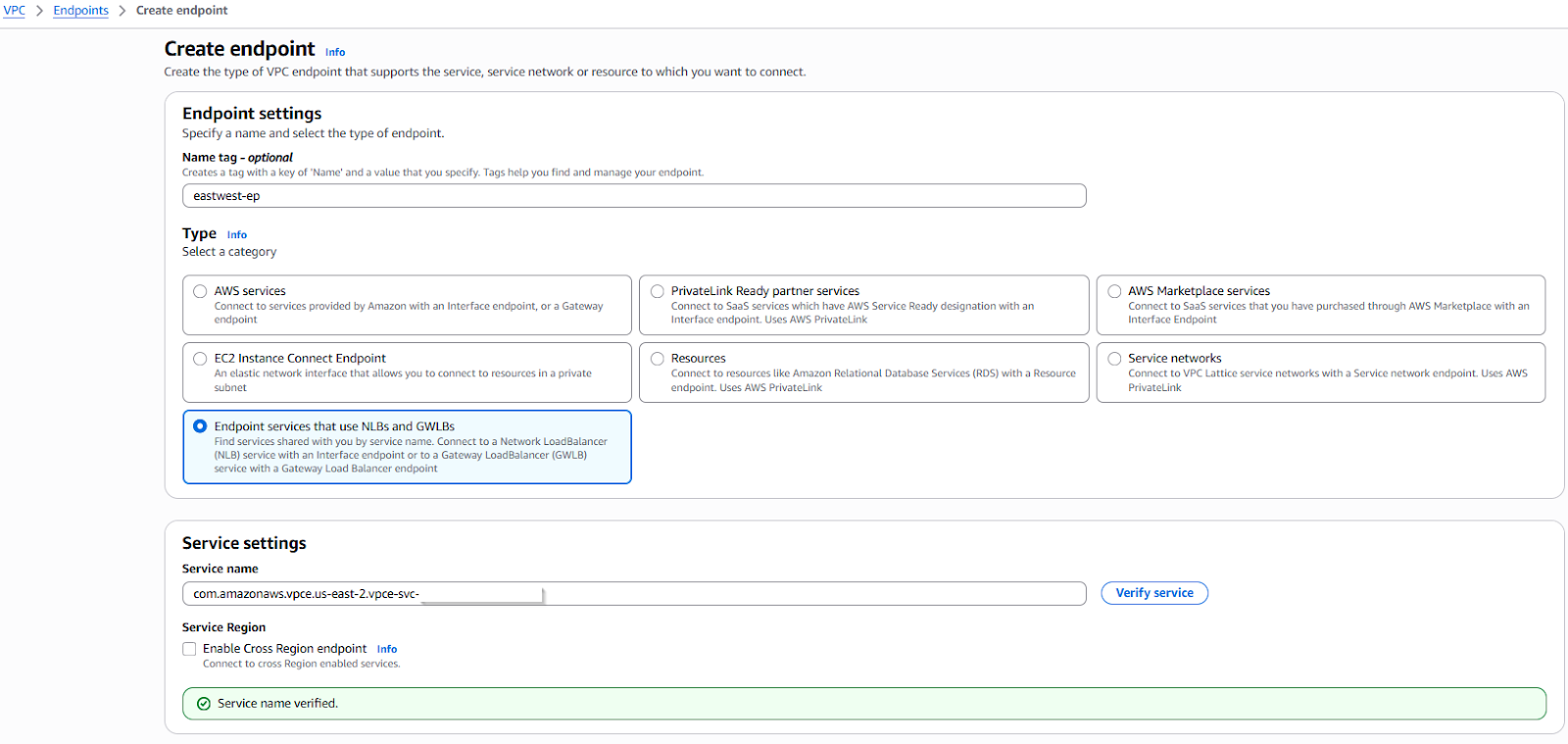
Step 2: Provision the Endpoints
- Navigate to VPC > Endpoints and select Create Endpoint.
- Type: Select Gateway Load Balancer.
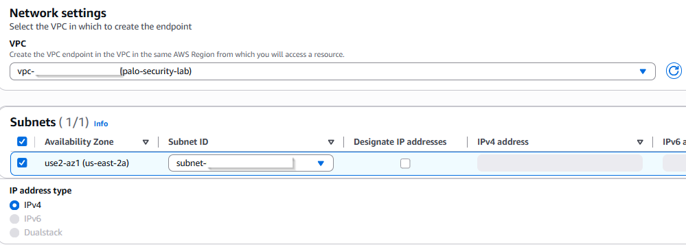
- Service Name: Paste the name copied in Step 1 and click Verify. Once verified it will show the available AZs and subnets select the appropriate ones.
Step 3: Repeat for Functionality
- Provision your first endpoint for East-West traffic.
- Provision a second endpoint for Outbound (Internet) traffic.
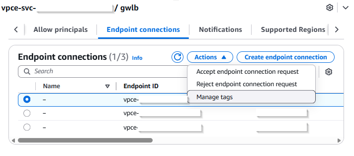
Step 4: Endpoint Acceptance
- Accept the connections back in VPC > Endpoint Services > Endpoint Connection
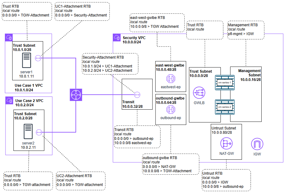
With all the infrastructure created so we can reference them now we can update or create our needed route tables.
Below are the VPC subnets all which have their own dedicated route tables assigned with the routes listed:
Security VPC
Trust
- Local route
Untrust
- Local route
- 0.0.0.0/0 > IGW
- 10.0.0.0/8 > outbound-ep
Transit
- Local route
- 0.0.0.0/0 > outbound-ep
- 10.0.0.0/8 > eastwest-ep
East-west-gwlbe
- Local route
- 10.0.0.0/8 > TGW attachment
Outbound-gwlbe
- 0.0.0.0/0 > NAT-GW
- 10.0.0.0/8 > TGW-Attachment
UC1 VPC
Trust
- 0.0.0.0/0 > TGW attachment
UC2 VPC
Trust
- 0.0.0.0/0 > TGW attachment
TGW Attachments
Here are the transit gateway attachments RTBs. Make sure after creating them to associate them like RTBs to Subnets.
Security-Attachment
- 10.0.1.0/24 > UC1-Attachment
- 10.0.2.0/24 > UC2-Attachment
UC1-Attachment
- 0.0.0.0/0 > Security-Attachment
UC2-Attachment
- 0.0.0.0/0 > Security-Attachment
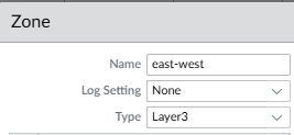
Now that the packets are arriving at the firewall, we need to define how the VM-Series handles them. We will use sub-interfaces and zones to keep our East-West and Outbound traffic logically separated.
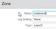
Zones
East-West
Outbound
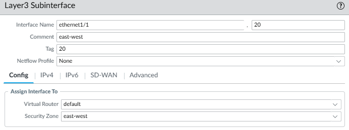
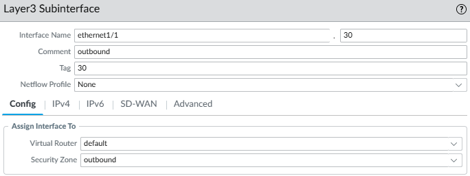
Sub-Interfaces
Adding to our previously .10 I am trying to keep things clean, so I’ve used a consistent ID scheme (e.g., .20 and .30) for the new sub-interfaces.
Assign them to the same VR and their correlating zone we just created.
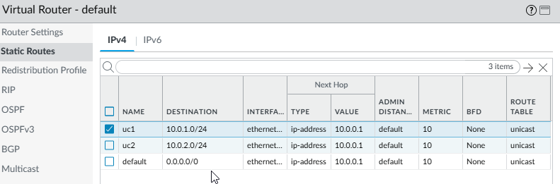
Routing
I have added the static routes here for reference if using IP and not Instances in the GWLB but the DHCP default route should work.
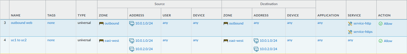
Policies
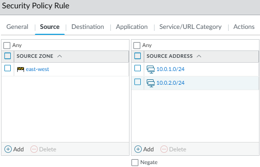
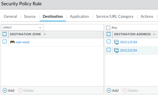
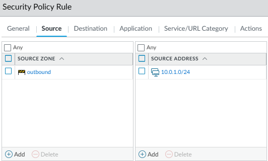
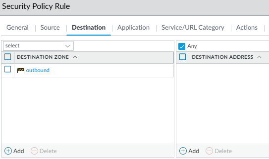
For this example I will allow all east to west communication and only allow UC1 web access to the internet.
East-to-west: I use one rule with both source and destination with those subnets but it can be more specific.
Outbound: In this rule I only allow UC1
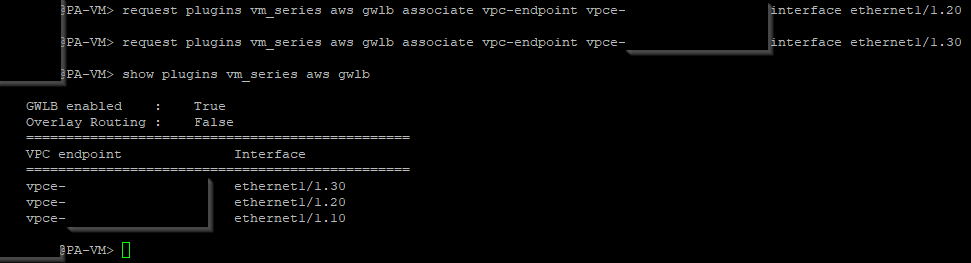
GWLBe associations
Associate the new GWLBes to their sub-interfaces, this is covered in more detail in the previous post.
With the routing and policies in place, all East-West and Outbound traffic should now hit the Palo Alto sub-interfaces.
- Centralized Outbound (UC1 → Internet)
Test: Accessing a web resource from Server 1 (UC1).
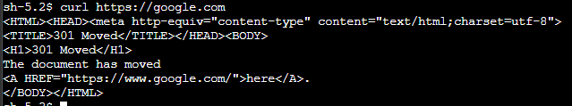
Result: Traffic is allowed per policy.
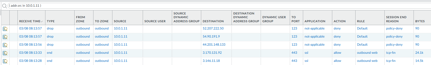
Notice in your VPC flow logs or Palo Alto traffic logs that the traffic is exiting through the Centralized NAT-GW in the Security VPC. You are no longer paying for a NAT-GW in every spoke.
- Policy Discrimination (UC2 → Internet)
Test: Attempting the same web access from Server 2 (UC2).
Result: Blocked/Dropped.
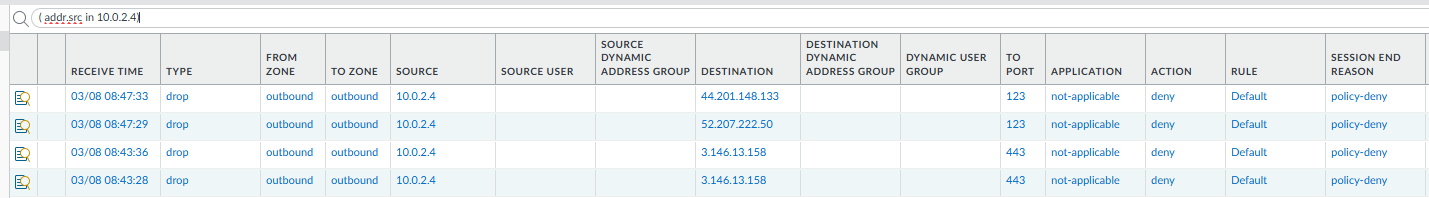
This proves that even though both VPCs use the same Hub, you can apply different security postures. UC1 has internet access; UC2 is isolated.
- East-West Inspection (UC1 ↔ UC2)
Test: Pinging and then SSHing from Server 1 to Server 2 and back.
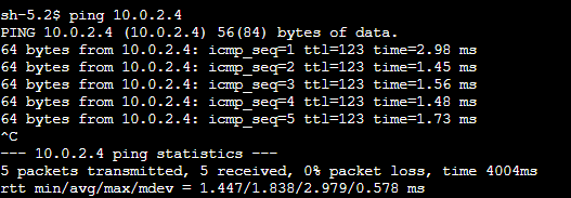
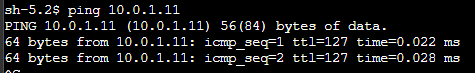
Result: Traffic is inspected on the Internal-Inspection zone (Sub-interface .20).
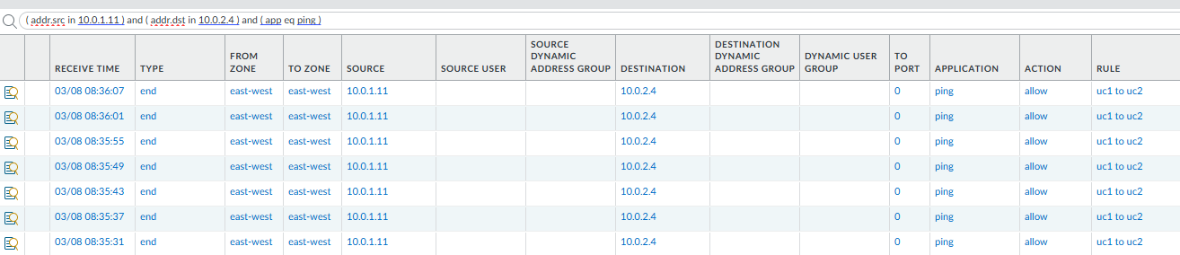

This confirms the Transit Gateway is successfully hair-pinning traffic through the GWLB for inter-VPC communication.
We have successfully migrated from a Distributed to a Centralized architecture. By moving the "Edge" of our network to a Transit Gateway hub, we’ve achieved:
- Cost Reduction: Consolidating NAT Gateways and Endpoints.
- Operational Simplicity: Managing zones and policies in one central location.
- Scalability: Adding a new "UC3" VPC now only requires a TGW attachment and a few route entries.
Next we will retire the NAT-GW and configure our Palo Alto VM-Series to perform the Source NAT for the entire hub. One less AWS service to pay for, and keeping more in the VM-Series.